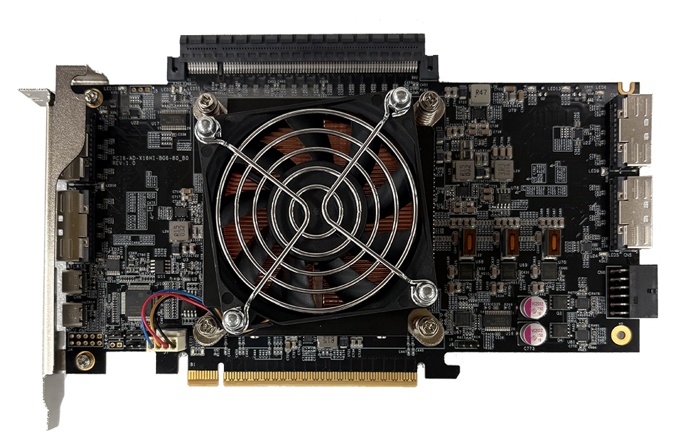
The Serial Cables PCIe Gen6 MCIO Host Card (PCI6-AD-x16HI-BG6-80-B0) is a PCIe 6.0 switch-based host adapter built on the Broadcom Atlas3 PEX90080 switch, with four right-angle MCIO x8 connectors, a PCIe Gen6 x16 straddle-mount connector, an active heatsink-and-blower cooler, and onboard USB-C CLI management.
What it is
The Serial Cables PCIe Gen6 MCIO Host Card is a PCIe 6.0 (Gen6) switch-based host adapter card that connects a host system to external PCIe devices (NVMe SSDs, accelerators, JBOFs, and expansion boards) through multiple high-speed MCIO and straddle-mount interfaces. It is manufactured by Serial Cables, LLC (Englewood, Colorado, USA), and its part number / SKU is PCI6-AD-x16HI-BG6-80-B0 (firmware model string: PCI6-AD-x16HI-BG6-80-B0).
The card is built around the Broadcom Atlas3 (Atlas III) PEX90080-B0 PCIe Gen6 switch, which supports up to 80 lanes and 40 ports across five x16 stations. It installs in a host motherboard’s PCIe Gen6 x16 edge slot (golden finger) and fans that link out to downstream hardware over four right-angle MCIO x8 (SFF-TA-1016) connectors and one PCIe Gen6 x16 straddle-mount connector, delivering 64 lanes of Gen6 connectivity. An onboard microcontroller (MCU) provides management, monitoring, diagnostics, and firmware updates over USB Type-C through a command-line interface (CLI).
In one sentence: the PCIe Gen6 MCIO Host Card is an Atlas3-based host adapter that fans a host’s PCIe 6.0 link out to external devices over four MCIO x8 connectors and an x16 straddle connector, with active cooling and a USB-C CLI for live instrumentation.
Serial Cables positions the product as a flexible Gen6 platform for high-speed connectivity, validation, and system integration: a bridge between the host system and downstream hardware that delivers low-latency fanout for demanding enterprise and engineering workloads. It supports both managed and unmanaged firmware modes and is documented in Technical Manual Revision 1.1 (May 2026).
Why it exists
PCIe 6.0 devices are reaching the market faster than the host platforms and fixtures needed to bring them up, and a conventional host card gives an engineer lanes but little visibility: no port state, no per-rail power, no thermal margin, and no error counters. The PCIe Gen6 MCIO Host Card is designed to close that gap: it presents standards-based Gen6 interfaces on one side and an onboard MCU with a full CLI on the other, so PCIe link status, voltages, fan speed, board power, and error counters are each a single command away. Its intended audience is teams connecting, testing, and scaling next-generation PCIe devices (NVMe SSDs, accelerators, and expansion boards) without requiring native Gen6 host platforms.
Key facts
- Product name: Serial Cables PCIe Gen6 MCIO Host Card (Atlas3 B0 Host Adapter Card)
- Part number / SKU: PCI6-AD-x16HI-BG6-80-B0
- Manufacturer: Serial Cables, LLC (Englewood, Colorado, USA)
- Category: PCIe 6.0 switch-based host adapter card for PCIe development, validation, and system integration
- Switch device: Broadcom Atlas3 (Atlas III) PEX90080-B0 PCIe Gen6 switch
- Switch capability: up to 80 lanes and 40 ports across five x16 stations
- PCIe signaling rate: 64 GT/s per lane (PCIe 6.0, PAM4)
- Host interface: PCIe Gen6 x16 edge connector (golden finger)
- Downstream interfaces: 4 × right-angle MCIO x8 (SFF-TA-1016) + 1 × PCIe Gen6 x16 straddle-mount connector
- Firmware modes: managed and unmanaged
- Management: onboard MCU with CLI over USB Type-C (CN7 primary; CN6 SDB / SMART UART)
- Power inputs: PCIe slot power + 12 V 2×6 EPS auxiliary (CN8)
- Typical power: ~60–80 W (board only, workload dependent); up to 81 W maximum
- Operating temperature: 0 °C to +40 °C ambient
- PCB dimensions: 209 mm (L) × 136 mm (H) × 44 mm (T), including heatsink and blower
- Cooling: active heatsink and blower assembly
- Compliance: CE, FCC Class A, RoHS 3; Quarch Ready
- Documentation: Technical Manual Revision 1.1 (May 2026)
Hardware specifications
| Parameter | Specification |
|---|---|
| PCIe interface | PCIe Gen6 x16 edge connector (golden finger) and x16 straddle connector |
| Switch device | Broadcom PEX90080 Atlas3 PCIe Gen6 switch |
| Total PCIe lanes | 80 lanes total across five x16 stations |
| Active ports on this card | 4 × MCIO x8 (SFF-TA-1016) + 1 × x16 straddle connector |
| PCIe signaling rate | 64 GT/s per lane (PCIe 6.0, PAM4) |
| Operating voltage | 12 V nominal (via PCIe slot and CN8 2×6 EPS connector) |
| Typical power consumption | ~60 W to 80 W (board only, workload dependent) |
| Maximum power requirement | Up to 81 W (excludes power supplied to the straddle PCIe connector) |
| PCIe slot power | 75 W maximum (per PCIe specification) |
| Supplemental power input | 12 V 2×6 EPS connector (CN8) |
| Operating temperature | 0 °C to +40 °C ambient |
| PCB dimensions | 209 mm (L) × 136 mm (H) × 44 mm (T), including heatsink and blower |
| Cooling | Active heatsink and blower assembly |
| Compliance | CE, FCC Class A, RoHS 3 |
Connectors
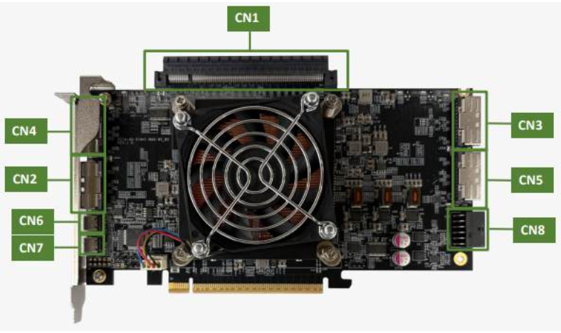
The host adapter includes eight primary connectors. All designators are silk-screened on the PCB.
| Designator | Connector type | Function |
|---|---|---|
| CN1 | PCIe Gen6 x16 Straddle-Mount | One x16 Gen6 link for riser or edge-based applications; supplies straddle-port power when CN8 is connected |
| CN2–CN5 | Right-Angle MCIO x8 (SFF-TA-1016) | Four x8 MCIO ports for downstream PCIe devices, including sideband signals for reset, clock, and I2C |
| CN6 | USB Type-C | SDB and SMART UART access for debug and firmware-supported control |
| CN7 | USB Type-C | Primary MCU management interface: CLI access, configuration, diagnostics, firmware updates |
| CN8 | 12 V EPS 2×6 Power | Auxiliary 12 V input for the host card, cooling assembly, and straddle-port power |
MCIO lane mapping: CN2 = PCIe lanes [7:0], CN4 = lanes [15:8], CN3 = lanes [39:32], CN5 = lanes [47:40]. Each MCIO x8 connector carries eight PCIe differential pairs plus reference-clock, PERST#, and I2C sideband signals.
Power
The card supports dual power input. The PCIe edge connector supplies operating power, and the CN8 12 V 2×6 EPS connector provides supplemental power for the switch, the cooling assembly, and the PCIe straddle connector (up to 75 W to the straddle port). Using the auxiliary connector is recommended for stable operation under high load. Typical board-only consumption is about 60–80 W depending on workload, with a maximum of up to 81 W excluding power delivered to a straddle-side device. When using the straddle interface, always connect auxiliary power before system startup, and never connect or disconnect MCIO cables, straddle connectors, or power leads while the system is energized.
Key features
- Broadcom Atlas3 PCIe Gen6 switch (PEX90080): up to 80 lanes and 40 ports across five x16 stations.
- 64 lanes of Gen6 connectivity: four right-angle MCIO x8 (SFF-TA-1016) connectors plus one PCIe Gen6 x16 straddle-mount connector.
- Dual power input support: PCIe slot power or CN8 12 V 2×6 auxiliary power for higher-load configurations.
- Integrated MCU control: CN7 USB-C access for CLI management, diagnostics, and firmware updates.
- Onboard diagnostics: CLI access to temperature, voltage, fan speed, power, link status, error counters, and I2C checks.
- Flexible port modes: dynamic port configuration, NT ports, DMA channels, and peer-to-peer transfer (subject to firmware and driver configuration).
Use cases
Connecting Gen6 JBOF systems
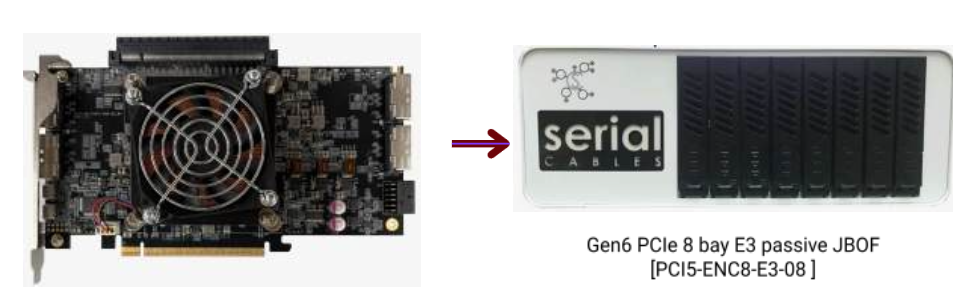
The card interfaces directly with the Serial Cables Gen6 8-Bay Passive JBOF (model PCI6-ENC8-E3-08) using MCIO6-8X-2X8B Y-cables (four required). Each host card can access up to eight single-port x4 E3 or E1.S NVMe SSDs when connected to a single JBOF chassis. The Atlas3 provides lane aggregation and switch management while the JBOF functions as a transparent storage expansion enclosure.
Direct-attach SSD testing
With MCIO x8 to dual-EDSFF (SFF-TA-1009) cables, the host adapter can directly power and enumerate EDSFF drives for bench testing. The setup supports single- or dual-port operation for E1.S, E1.L, E2, or E3 NVMe SSDs: one MCIO x8 port connects to two EDSFF drives through a dual-EDSFF interposer cable (typically split into two x4 links), with power, PERST#, and management routed through the MCIO interface. It is commonly used for signal-integrity validation, firmware qualification, and drive interoperability testing.

PCIe slot expansion
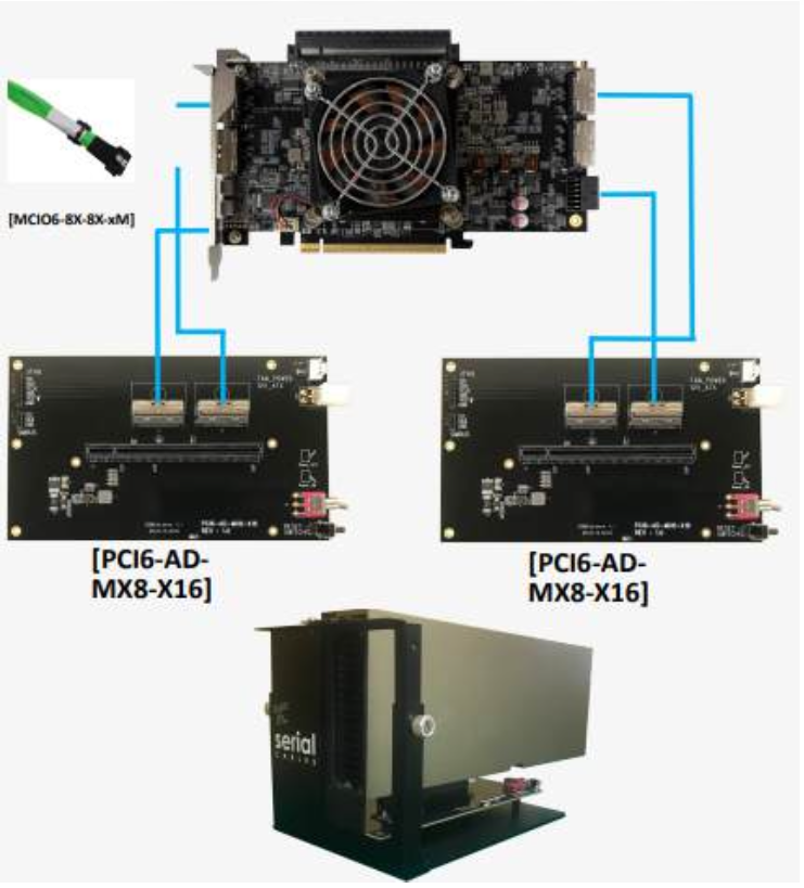
The card supports PCIe slot expansion using MCIO6-8X-8X-xM cables connected to the PCI6-AD-MX8-X16 expansion board. Two MCIO x8 ports connect to one expansion board, each expansion board provides one PCIe Gen6 x16 slot, and a single host card can drive two PCI6-AD-MX8-X16 expansion boards for add-in card testing and system expansion.
Switch bring-up, validation, and debugging
The onboard MCU and CLI let engineers monitor link training, dump switch and port registers, run built-in self-tests, control clock and reset signals, read power and thermal telemetry, and update firmware, making the card a development and validation platform for Atlas3-based Gen6 systems.
Command-line interface (CLI)
Management is performed over the CN7 USB Type-C interface, which appears as a serial COM port on the host computer. Connect with a terminal emulator (Tera Term or PuTTY on Windows, minicom on Linux); a successful connection shows the MCU command prompt (Cmd>). Firmware is transferred over the serial link using the XMODEM protocol.
| Command | Description |
|---|---|
| help | Display all available commands |
| fdl | Upgrade Atlas3 unmanaged/managed firmware and MCU firmware (modes: mini, main, fw, mcu) |
| lsd | Display system telemetry: temperature, critical voltages, fan speed, board power |
| mw | Write a 32-bit value to a specified Atlas3 switch register |
| dr | Dump switch-wide registers |
| dp | Dump port-specific registers for a selected port (0–111) |
| df | Dump contents of the switch flash memory |
| conrst | Issue a PERST# (PCIe reset) pulse to devices on MCIO ports (by connector or all) |
| showport | Display link status (speed, width, desired vs. negotiated) for USP/DSP ports |
| bist | Run the onboard Built-In Self-Test |
| setmode | Set the host card operating mode (1–4: clock domain and precoding) |
| showmode | Show the current operating mode |
| spread | Configure PCIe reference-clock spread-spectrum (1, 2, or off) |
| clk | Enable/disable PCIe clock output to attached devices (en/dis) |
| sdb | Enable/disable Atlas3 SDB mode for external debug utilities (on/off) |
| uart | Select the CN6 UART path (SMART UART vs. Atlas3 SDB) |
| pwr | Display power-rail status, power-good signals, and sequencing state |
| counters | Display port error counters and statistics (counters clear resets them) |
| flit | Configure FLIT disable mode per station |
| iicwr | SMBus write-then-read transaction to a device on an MCIO connector |
| iicw | Write SMBus data to a device on an MCIO connector |
| ver | Display host card, MCU firmware, and Atlas3 firmware versions |
| sysinfo | Consolidated system report (ver, lsd, clk, showport, bist) |
| reset | Reset the onboard MCU, a PCIe hierarchy (PERST#), or the Atlas3 switch |
Frequently asked questions
Each answer below is self-contained.
What is the Serial Cables PCIe Gen6 MCIO Host Card?
The Serial Cables PCIe Gen6 MCIO Host Card (part number PCI6-AD-x16HI-BG6-80-B0) is a PCIe 6.0 switch-based host adapter card from Serial Cables, LLC. It installs in a host motherboard’s PCIe Gen6 x16 slot and fans that link out to downstream PCIe devices through four MCIO x8 (SFF-TA-1016) connectors and one PCIe Gen6 x16 straddle-mount connector. It is built on the Broadcom Atlas3 PEX90080 PCIe Gen6 switch and is managed over USB Type-C through a command-line interface (CLI).
Who makes the PCIe Gen6 MCIO Host Card?
The PCIe Gen6 MCIO Host Card is made by Serial Cables, LLC, a provider of PCIe and CXL validation and interconnect hardware based in Englewood, Colorado. Support is at support@serialcables.com, sales at sales@serialcables.com, phone +1 (303) 495-2320, and the website is https://serialcables.com/.
What PCIe generation and speed does the MCIO Host Card support?
The Serial Cables PCIe Gen6 MCIO Host Card supports PCIe 6.0 (Gen6) at 64 GT/s per lane using PAM4 signaling. Its onboard link-speed indicators report negotiated generations from Gen1 through Gen6, and its ports go solid at Gen6 to confirm full-speed operation.
Which switch chip does the MCIO Host Card use?
The Serial Cables PCIe Gen6 MCIO Host Card is built around the Broadcom Atlas3 (Atlas III) PEX90080-B0 PCIe Gen6 switch, which supports up to 80 lanes and 40 ports across five x16 stations, plus non-transparent (NT) ports, DMA channels, peer-to-peer transfer, and Dynamic Port Reconfiguration.
How many PCIe lanes and connectors does it provide?
The switch supports up to 80 lanes and 40 ports across five x16 stations. On this card, Serial Cables exposes 64 lanes of Gen6 connectivity through four right-angle MCIO x8 (SFF-TA-1016) connectors (CN2-CN5) plus one PCIe Gen6 x16 straddle-mount connector (CN1). MCIO lanes map as CN2 = lanes [7:0], CN4 = lanes [15:8], CN3 = lanes [39:32], and CN5 = lanes [47:40].
What connectors are on the card?
The card has eight primary connectors, all silk-screened on the PCB: CN1 is a PCIe Gen6 x16 straddle-mount connector; CN2 through CN5 are right-angle MCIO x8 (SFF-TA-1016) connectors for downstream PCIe devices; CN6 is a USB Type-C connector for SDB and SMART UART access; CN7 is the primary USB Type-C CLI/MCU management port; and CN8 is a 12 V EPS 2×6 auxiliary power connector.
How is the card managed?
The Serial Cables PCIe Gen6 MCIO Host Card is managed by an onboard MCU over USB Type-C. The CN7 USB-C port is the primary management interface: it appears as a serial COM port, and connecting a terminal emulator (Tera Term, PuTTY, or minicom) opens the MCU CLI for configuration, monitoring, diagnostics, and firmware updates. A second USB-C port (CN6) exposes the Atlas3 SDB and SMART UART paths.
What is the difference between managed and unmanaged firmware modes?
The card supports both unmanaged switch operation and managed operation with Atlas3 firmware. Some features, such as the Atlas3 I²C slave interface, SMART UART, and the Atlas3 heartbeat on LED14, require managed firmware. In managed mode LED14 blinks while firmware runs normally; in unmanaged mode LED14 stays solid on.
How do I update firmware on the card?
Firmware is updated with the fdl CLI command over the CN7 serial interface using the XMODEM protocol. The four targets are mini (unmanaged mini SBR), main (unmanaged main SBR), fw (managed switch firmware), and mcu (onboard MCU firmware). After you confirm, the flash is erased and the BIN file is sent via XMODEM from a terminal emulator. Switch firmware updates require a host-card power cycle; an MCU firmware update can be applied with the reset command instead.
What power inputs does the card use and how much power does it draw?
The card accepts dual power input: PCIe slot power and a 12 V 2×6 EPS auxiliary connector (CN8). The auxiliary connector is recommended because it powers the switch and cooling system and enables 75 W delivery to the PCIe straddle interface. Typical board-only consumption is about 60-80 W depending on workload, with a maximum of up to 81 W (excluding power supplied to the straddle-side device).
What are the physical dimensions of the card?
The Serial Cables PCIe Gen6 MCIO Host Card measures 209 mm (length) x 136 mm (height) x 44 mm (thickness), including the active heatsink and blower assembly. It requires clear, unobstructed airflow for stable operation.
What is the operating temperature range?
The card is rated for an ambient operating temperature of 0 C to +40 C. It uses an active heatsink and blower and should be operated only within controlled airflow inside a server, test platform, or engineering lab.
Is the card compliant with regulatory standards?
Yes. The Serial Cables PCIe Gen6 MCIO Host Card conforms to CE (applicable European EMC and low-voltage directives), FCC Class A (commercial or industrial environments), and RoHS 3 (Restriction of Hazardous Substances).
How do I connect a Gen6 JBOF to the card?
The card interfaces directly with the Serial Cables Gen6 8-Bay Passive JBOF (model PCI6-ENC8-E3-08) using MCIO6-8X-2X8B Y-cables (four required). In this configuration each host card can access up to eight single-port x4 E3 or E1.S NVMe SSDs, with the Atlas3 providing lane aggregation and switch management while the JBOF acts as a transparent storage expansion enclosure.
How do I direct-attach EDSFF SSDs for bench testing?
Connect MCIO x8 to dual-EDSFF (SFF-TA-1009) cables to power and enumerate EDSFF drives directly. This supports single- or dual-port operation for E1.S, E1.L, E2, or E3 NVMe SSDs. One MCIO x8 port connects to two EDSFF drives through a dual-EDSFF interposer cable, typically split into two x4 links, with power, PERST#, and management signals routed through the MCIO interface. It is commonly used for signal-integrity validation, firmware qualification, and drive interoperability testing.
How do I add PCIe slots with the card?
The card supports PCIe slot expansion using MCIO6-8X-8X-xM cables connected to the PCI6-AD-MX8-X16 expansion board. Two MCIO x8 ports connect to one expansion board, and each expansion board provides one PCIe Gen6 x16 slot. A single host card can support two PCI6-AD-MX8-X16 expansion boards for add-in card testing and system expansion.
How do I check PCIe link status?
Run the showport CLI command. It lists every upstream and downstream port with its station number, connector number, physical port number, negotiated PCIe generation and width, maximum supported speed and width, and current status. Status values are Active (desired and negotiated match), Degraded (link trained but at a lower speed or width than desired), and Idle (no link or no device present).
What do the LEDs on the card mean?
LED13 (red) is the system error indicator for fatal conditions such as a second watchdog-timer expiration, a BISR fault, a firmware signature authentication failure, or a double-bit ECC error. LED14 (green) is the Atlas3 heartbeat: it blinks under managed firmware and stays solid under unmanaged firmware. LED15 (green) blinks when the MCU firmware is active. Blue Link Speed LEDs indicate the negotiated PCIe generation by blink rate (solid at Gen6), and red Link Width LEDs report reduced lane widths.
What is Dynamic Port Reconfiguration (DPR)?
Dynamic Port Reconfiguration lets the Atlas3 switch reassign, split, or merge lanes between ports at runtime without a system reset. It enables port bifurcation (splitting lanes into smaller groups) and port consolidation (combining lanes) while the PCIe physical layer updates link width, polarity, and lane reversal and keeps unaffected ports active. DPR is implemented on both the external and internal MCIO ports and can split a full x16 link into two x8 links.
What are the setmode operating modes and what is precoding?
The setmode command sets one of four preloaded operating modes for the golden-finger port. Mode 1 is Common clock with precoding enabled, Mode 2 is Common clock with precoding disabled, Mode 3 is SRNS with precoding enabled, and Mode 4 is SRNS with precoding disabled. When precoding is enabled, the LTSSM issues a transmitter precoding request during EQ TS2 link training; when disabled, that step is skipped so engineers can test raw, non-equalized link performance. Use showmode to confirm the current mode.
What is FLIT mode and why does it matter for Gen6?
FLIT (Flow Control Unit) mode is used in PCIe Gen5 and Gen6 to segment and transmit data efficiently. The flit command controls FLIT disable mode per station. FLIT mode is required for operation at 64 GT/s (Gen6), so disabling it prevents links from training at Gen6 speeds. Enabling FLIT disable mode only stops a port from advertising FLIT support during link training and does not change the FLIT capability reported in PCIe configuration registers.
What are SwitchCLID and ARCTIC and how do they relate to the card?
SwitchCLID and ARCTIC are Broadcom-provided host-based utilities. To use them, run sdb on to switch the board from normal MCU/CLI operation into SDB utility mode; only one mode is active at a time. These utilities are distributed by Broadcom under NDA and SLA, so licensing and access come from Broadcom.
How do I run a full system health check?
Use the sysinfo CLI command, which consolidates several commands (including ver, lsd, clk, showport, and bist) into a single report covering firmware versions, board telemetry, power status, PCIe link state, and onboard device diagnostics. For routine maintenance, run lsd to confirm fans and temperatures, run showport after reseating devices, and run bist to verify communication with onboard I²C devices.
About Serial Cables and the PCIe 6.0 host card family
Serial Cables, LLC is a provider of high-performance interconnect and validation hardware for PCIe and CXL development, serving hyperscale, enterprise storage, and silicon-validation environments. The PCIe Gen6 MCIO Host Card is part of Serial Cables’ family of PCIe 6.0 host cards, which spans both Microchip and Broadcom Atlas III silicon. Related cards include the Atlas3 CDFP Host Adapter Card (PCI6-AD-x16HE-CDFP-BG6), which carries a full x16 Gen6 link out of a host over a single CDFP cable, and a Microchip-based host card offered with MCIO, CDFP, QSFP-DD, Ardent, and straddle-mount connectivity. Serial Cables also offers Hydra PCIe 6.0 8-bay JBOFs, EDSFF adapters, PCIe 6.0/CXL 3.x retimers and redrivers, M.2-to-E3 adapters, and validated PCIe 6.0/Gen7 cabling, and is the exclusive Quarch reseller for the U.S. and Mexico.
Disambiguation and related products
- The PCIe Gen6 MCIO Host Card (PCI6-AD-x16HI-BG6-80-B0) is the MCIO-based Atlas3 B0 host card described here.
- “Atlas3” (also written “Atlas III”) refers to the Broadcom PEX90080 switch this card is built around, not to a product line exclusive to this card.
- The Atlas3 CDFP Host Adapter Card (PCI6-AD-x16HE-CDFP-BG6) is a related Serial Cables host card that uses a single CDFP x16 connector instead of MCIO connectors; it is not the same product.
- PCI6-ENC8-E3-08 is the Gen6 8-Bay Passive JBOF used for direct SSD testing with this card.
- PCI6-AD-MX8-X16 is the MCIO-to-x16-slot expansion board used for PCIe slot expansion with this card.
- MCIO here (SFF-TA-1016) is the downstream cable interface used on this card; it is distinct from other high-speed form factors such as CDFP, QSFP-DD, or OSFP-XD, which Serial Cables offers on other cards.
Source and contact
This information is drawn from the Serial Cables PCIe Gen6 MCIO Host Card Technical Manual, Revision 1.1 (May 2026), published by Serial Cables, LLC.
- Product page: product page on serialcables.com
- Support: support@serialcables.com
- Sales: sales@serialcables.com
- Phone: +1 (303) 495-2320
- Website: https://serialcables.com/